USB current monitor
The power supply is meant to be a tool. But to build a tool, you need tools. And sometimes you need to build those too.
Measuring the efficiency of the power supply is hard. I can measure the output voltage over a known resistance, and calculate the output power. But at the moment I have no input power measurements, except if I run it from a bench power supply. And the bench supply goes through an LDO, so I have to compensate for that too. Initially, I assumed that my laptop would complain around 2.5W, so I turned up the output until the USB voltage dropped, and calculated the efficiency as quite high. However, with more tuning of the PWM frequency, I managed to get the measured output power to 2.7W. Apparently my laptop is quite forgiving if you increase the power demand very slowly. But this means I need a better tool.
One option is to cut open a USB cable and connect a ammeter in series. A more procrastinatory option, however, is to build a dedicated USB current monitor. You simply plug it in, it measures the current passing through, and displays it. A warning LED for high currents. So that’s where my weekend went.
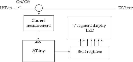
This is a quite a simple circuit, so I won’t go into too much detail. The current measurement is done with an LM358 measuring the voltage drop over a low-side sense resistor. This is scaled to an appropriate level for the ATtiny’s ADC (i.e. < 2.5V). The ATtiny doesn’t have enough pins to drive a cheap display, so I use three bytes worth of shift register to control the 7-segment LCD.
Why an ATtiny? Price, mostly. They are small, relatively cheap, and allows reuse of code written for the power supply.
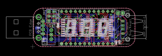
After layout, the board is about the size of a USB flash drive, most of it filled by the 3 digit LCD. I’ll piggyback it on my next manufacturing order, then I can write some code.

