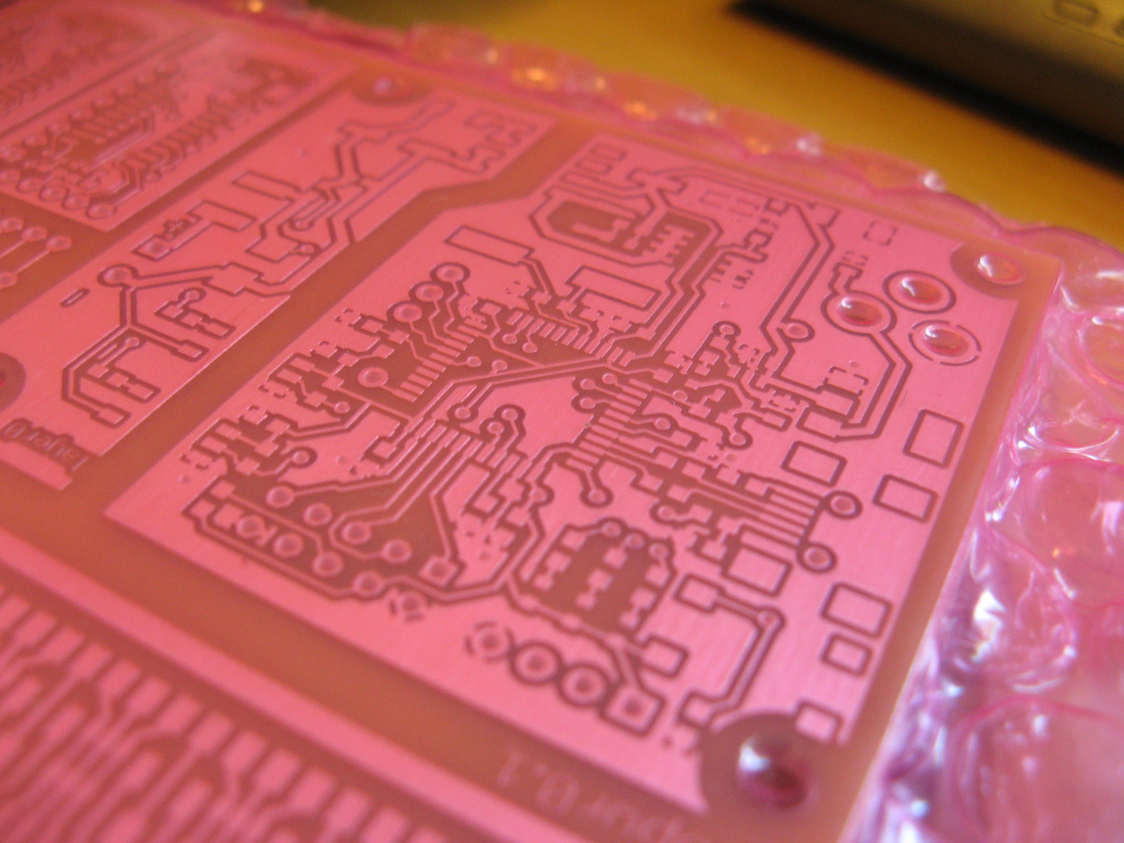
My current monitoring on rev0.1 was a bit optimistic, so I’m complicating the isolated side by adding more opamps. Half an LM358 is used to sense the return current, the other half acts as V-I converter, driving a BJT through the optocoupler, here simulated with an LED.

To test it, I need a variable voltage source –  rev0.1 is already useful enough.

Testing current measurement

I have since simplified this design – LM358 can supply enough output current – no BJT is required.

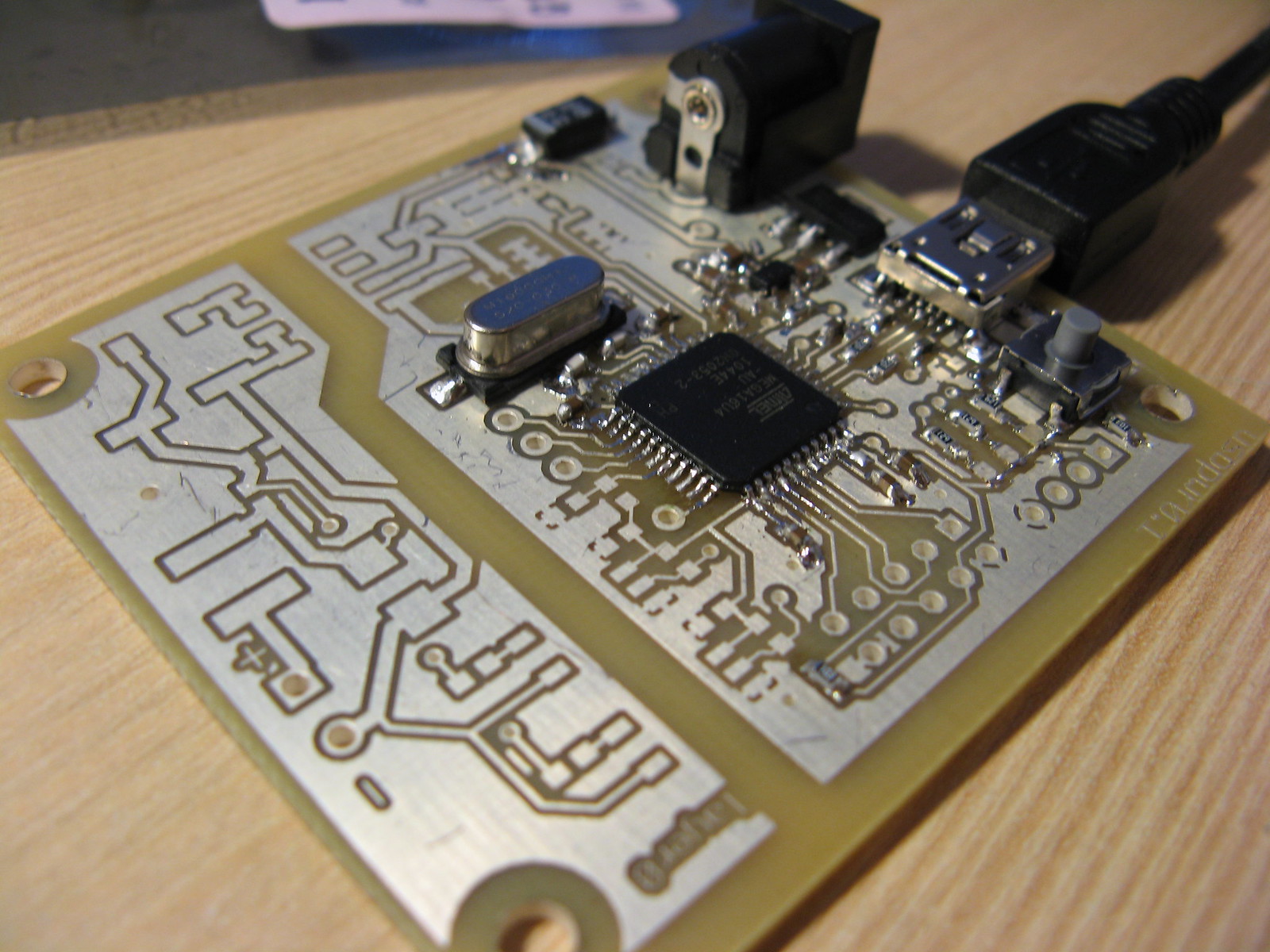
USB connection to ATmega16u4 is working: serial for controlling the main application, and USB DFU (device firmware upgrade) to load the bootloader.

I’m using Dean Camera’s LUFA library for the main program – it was quick to adapt to my application, and so far it is working well.

The bootloader is the default Atmel bootloader.  By pulling the !HWBL pin low at startup, execution jumps to the bootloader, allowing off-the-shelf software to be used for updating the device.  One less thing to manage.

Minimal USB board

While the design process is lots of fun, it is important to keep track of how feasible the final design is in terms of usability and production.  I’ve therefore come up with the following requirements – if they can’t be met, there is no point in me turning this into a product.

At least 2W output

I can calculate the theoretical losses to some extent, but until I build and measure it, I don’t really know how efficient it is.  I feel 2W is an attainable figure, and it is enough to be useful.

BOM cost < $25

Officially, I’d like the BOM to be as cheap as possible, but designing becomes a lot easier if you have some budget you are working from.  $25 sounds like a lot, right? I thought so too when I only looked at ICs, but when I added a connector or two, and then the transformers, then considered dials and a display, the budget looked much less forgiving.