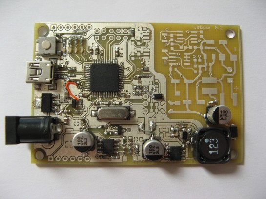
v0.2 bringup
I’ve started soldering the v0.2 board, testing and porting the v0.1 software as I go along. The LED, button, and ADC channels all moved, which required adjustment of a couple of header files. Two minor wire mods were required, but so far everything tested is working. There is a tiny bit of coupling between the PWM signal and the ADC feedback signal, but I suspect a well placed capacitor will clean the line up.
From here, I have to do the following:
- Populate the auxiliary transformer and generate a sane voltage rail for the opamps on the secondary side.
- Populate the feedback circuitry.
- Adjust the ADC driver to use the new configuration.
- Calibrate.
And then I can test my primary side current monitoring.
